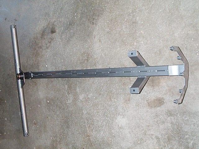
The Griggs Severe Duty torque arm.
-J
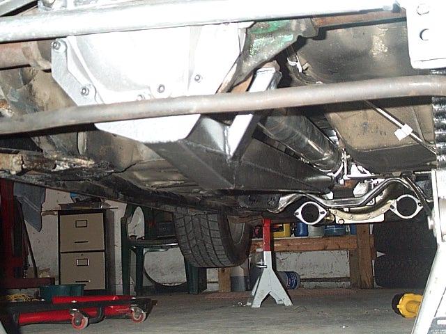
Various pictures of the torque arm, and how it fits in. It gets rather "busy" under there.
As you can see, it is a NICE kit. everything fits together just how
it should, and all the parts were there this time (thanks), including
2 sets of instructions.
-J
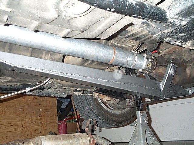
At last. The torque arm is in. Here are some shots of it installed, and
a few notes. The torque arm install really is fairly simple. One thing
they don't tell you in the directions, but is important... It is better
to put the bar closer to the floor of the car than it is to hang it low.
What happened to me was my subframes were welded in about 1/2" too close
together (towards the center of the car), so the cross brace for the
torque arm didn't fit straight across. As it turns out, it is okay
that it didn't, as putting it closer to the floor of the car actually
improved the geometry some. I also had the added bonus of it being
tucked up in out of the way more. I confirmed all this by talking to
Griggs Racing tonight on the phone.
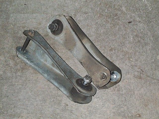
This pic is, of course the rear upper control arms that Ford chose from the factory to hold your rear end in your car, and control lateral movement, as well as pinion angle. The huge rubber bushings don't do much of a job of holding anything anywhere, but are needed to keep the rear end from binding up too terribly. The rear arms in a factory Fox-3 chassis are not parallel, or the same length. When the rear axle moves up and down, the geometry changes... really not a good setup for the best traction, but cheap, indeed.
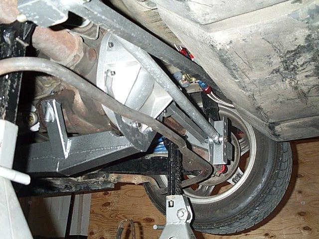
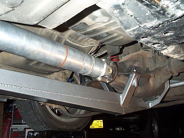
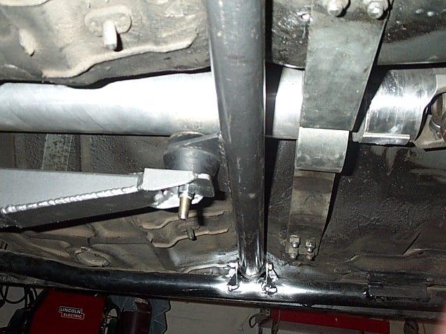
This is looking in from the driver's side between the wheels. What you see is the bushing, the cross bar, and the front of the torque arm.
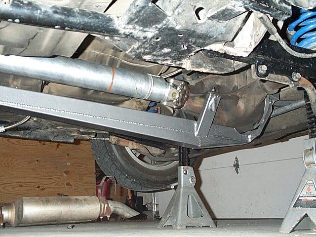
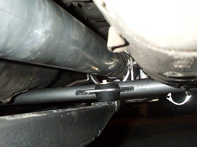
This picture shows the clearance between the safety loop, and the cross brace for the Torque Arm.
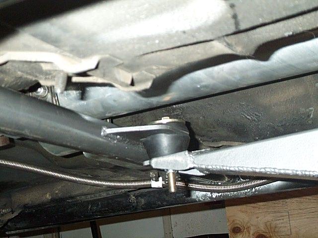
Another rear of the back end... with something missing. I swear the suspension sighed relief when I took out the upper control arms.

Here is a better pic of where the upper control arms WERE!!
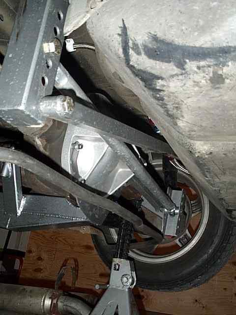
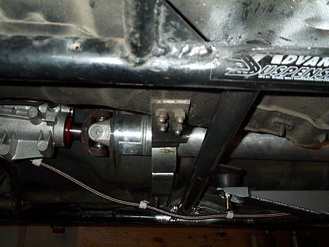
This is a view from the back, looking forward. A Griggs arm WILL clear the FMS driveshaft, you just need to cut the top bushing back a little bit (.5"). This gives plenty of clearance between the arm mount and the driveshaft. If it doesn't, you may need a new transmission mount-- the piece between the crossmember, and the actual transmission.
This pic is looking from the front to the back of the car.
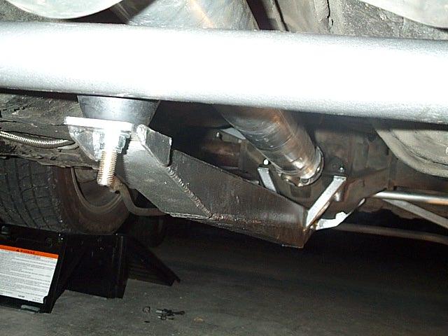
A pic from the passenger side... again showing ther are no clearance
problems. And, yes... I only had silver paint around. I'll hit it with some
black later :)
-J